A PTO shaft works by connecting the tractor Power Take-Off stub to the implement input shaft through a telescoping cardan shaft assembly that transmits rotational torque continuously while accommodating the changing angle and distance between the two connection points. Power flows from the tractor engine, through the tractor gearbox, out the PTO stub, through the shaft, and into the implement gearbox. The T сериялы PTO жетек білігі range transmits this power at 540 rpm or 1,000 rpm depending on the application.
The Eight-Component Power Path
Power enters the shaft at the splined yoke (component 4), which engages the tractor PTO stub. From there it flows through the first cross joint (component 1) — the universal joint that allows the shaft to transmit torque through an angle. The cross joint transfers power to the outer tube yoke (component 5) and into the outer tube (component 7). The inner tube (component 8) slides inside the outer tube, transmitting torque through the matching tube profile while allowing axial movement. Power then flows through the inner tube yoke (component 6), through the second cross joint, and out through the implement-end splined yoke into the implement gearbox.
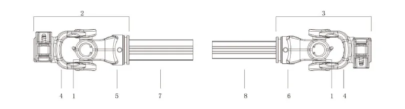
Each component has a specific function in the torque path. The cross kits are the designed failure point under overload.
How the Cross Joint Allows Angular Transmission
A simple cardan joint — one cross kit and two yoke bodies — allows the shaft to transmit torque through an angle. However, a single joint introduces a velocity variation at the output: the output shaft rotates faster and slower alternately with each revolution, at a frequency proportional to the operating angle. This variation is imperceptible at low angles but causes vibration at angles above approximately 6 degrees.
The T Series and L Series shaft uses two joints — one at each end of the telescoping tube — with the tube yokes assembled 90 degrees out of phase. When both joints operate at equal angles and in correct phase, the velocity variations cancel out, producing smooth constant-velocity power transmission at the implement input. This is why correct yoke phasing after cross-kit replacement is critical.
Why the Shield Does Not Rotate
The safety shield encloses the rotating shaft but does not rotate with it. A plastic sliding bearing at each shield end allows the shaft to spin freely inside the stationary shield. The safety chains anchor the shield to fixed, non-rotating points on both tractor and implement, preventing the shield from rotating even if the plastic bearing seizes.
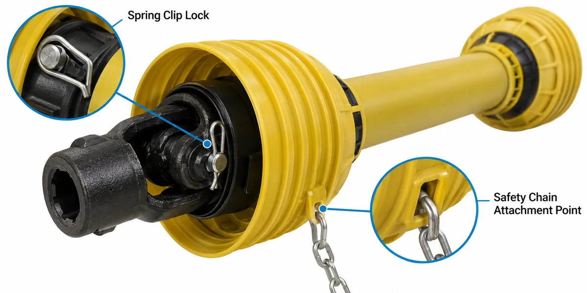
The shield is anchored by safety chains at both ends. If the plastic bearing seizes, the chains prevent the shield from rotating.
The Telescoping Tube: Accommodating Length Changes
As the implement rises and falls on the three-point linkage, the distance between the tractor PTO stub and the implement input shaft changes continuously. The telescoping tube accommodates this by allowing the inner tube to slide axially inside the outer tube. The torque-transmitting profile — triangular for T Series, lemon for L Series — ensures the tubes cannot rotate relative to each other while still allowing smooth axial slide.
See the Full T Series Component Specifications
Assembly diagrams, component part numbers, and torque tables for all 12 T Series models.
Тегтер
how does PTO shaft workPTO shaft mechanicscardan shaft operationPTO shaft componentsPTO power transmission