Identifying PTO shaft size requires three separate measurements: the spline profile at the tractor end (which determines compatibility), the torque class required by the implement (which determines the series), and the correct shaft length for the tractor-implement combination. Getting all three right ensures the replacement shaft fits, transmits the correct power, and lasts through the season.
Step 1: Identify the Spline Profile
Count the spline ridges on the tractor PTO stub — the short rotating shaft protruding from the rear of the tractor gearbox. Six splines: you have a 1-3/8 inch Z6 stub (540 rpm standard). Twenty splines: you have a 1-3/4 inch Z20 stub (1,000 rpm standard). Twenty-one splines: you have a 1-3/8 inch Z21 (less common, some European tractors).
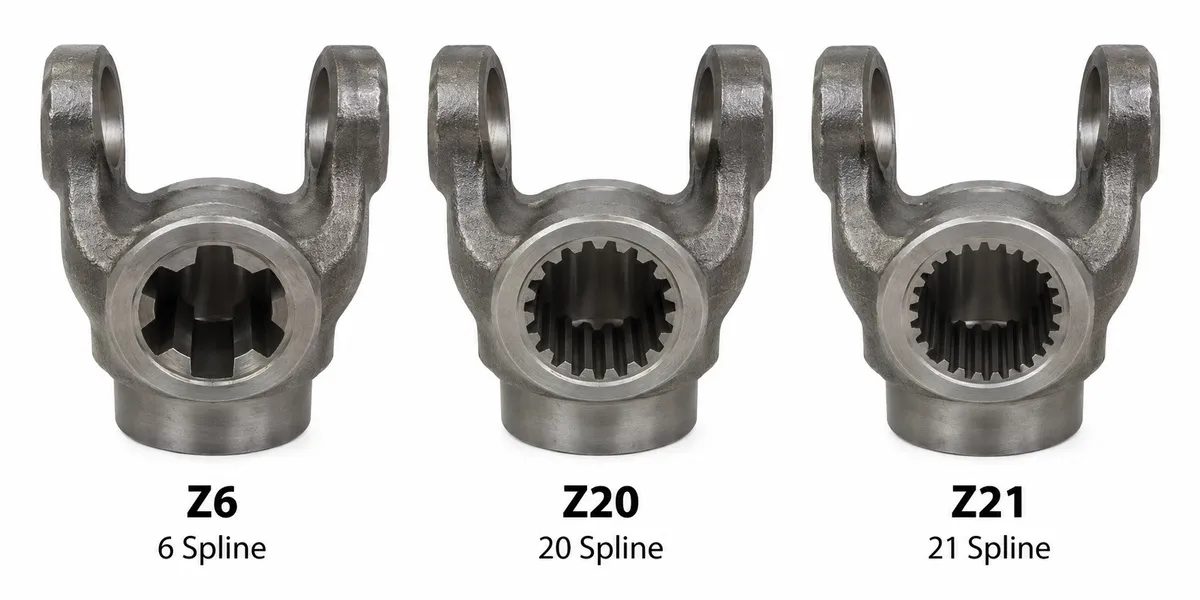
Counting splines takes 30 seconds and completely determines which yoke profile you need.
Step 2: Measure the Stub Diameter
If the stub condition makes spline counting difficult, measure the major diameter (the outer tip of the splines) with a digital caliper. A 1-3/8 inch (34.9 mm) measurement indicates Z6 or Z21. A 1-3/4 inch (44.5 mm) measurement indicates Z20. If the measurement reads 34.9 mm, count the splines to distinguish Z6 from Z21 — both have the same outer diameter but different spline counts and are not interchangeable.
Step 3: Determine the Required Torque Class
The torque class is determined by the implement power demand. Calculate: Torque (Nm) = Implement power (kW) × 9,549 ÷ PTO speed (rpm). Add 20% safety margin. Select the lowest T Series or L Series model where the Nm@PTO speed rating meets or exceeds your adjusted figure. See the T Series torque table or L Series torque table for complete data.
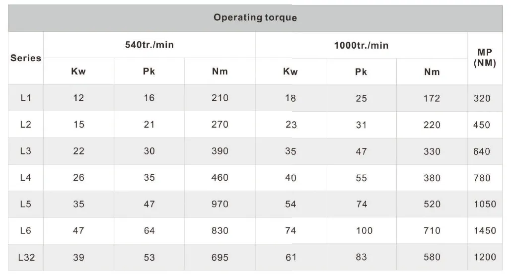
Use Nm@540 for standard PTO. Use Nm@1,000 for high-speed PTO. Always add 20% to the implement demand before selecting.
Step 4: Measure the Correct Shaft Length
- 1
Connect the implement to the tractor at normal working height.
- 2
Measure the coupling centre distance: tractor PTO stub face to implement input shaft face.
- 3
This is your reference dimension. Stock shaft compressed length should be 50 mm shorter.
- 4
Raise implement to maximum height. Verify at least 50 mm tube overlap remains.
- 5
Lower to minimum height. Verify tubes do not bottom out and 80 mm engagement remains.
- 6
If stock lengths do not fit, order a custom OEM length (MOQ 50 pcs, 25–30 days).
Reading the Existing Shaft Markings
Many shafts carry a series marking or part number stamped or labelled on the tube yoke or the shield. Look for labels such as T5, L5, Series 5, or a cross-kit dimension (e.g. 30.2×80). The series number directly corresponds to the T Series or L Series designation. If the shaft has a part number from another manufacturer, cross-reference using the cross-kit pin diameter and journal length — these are universally standardised dimensions.
Send Your Tractor and Implement Details — We Identify the Correct Size
Ever-Power Drive Line confirms the correct series, spline profile, and shaft length for your combination. Response within 24 hours.
Tags
how to identify PTO shaft sizePTO shaft size identificationPTO shaft sizingPTO spline countPTO series selection